Sprinklers ES – 20PC
October 12, 2023
Solanoid Box
October 12, 2023DFDS Spray Nozzle
Dry Fog Nozzles operate on a very sophisticated process which is based on two steps:
In the first one tiny water jets are injected into an high speed air flow which provides a first break up and atomization of the fluid.
In the second step the two phase flow, air entraining liquid droplets, goes trough a field of sound waves which produce a further break up and a lower droplet dimension.
This is realized through an impact between the two phase flow and a resonator located in front of the nozzle orifice.
₹0.00
Out of stock
Dry For Nozzles can only be manufactured with high precision machining operations but offer the following remarkable advantages.
A: The droplets in the atomized jet show low values for the Sauter Mean Diameter, and in addition a rather narrow range of individual droplet diameter: in other words the drops are very small and with little difference in diameter between the smallest and the biggest droplet. This means the spray is made by droplets very small and very similar in size, which is very important in all evaporative processes like for example air humidification: it is rather easy then to obtain values for the evaporation time and evaporation length of a given spray.
B: The noticeable variations in local air pressure all around the resonator, associated to the sound waves, eliminate the danger of dust and foreign particles build-up in the vicinity of the nozzle orifice, thus avoiding a decay in the atomizer performance.
The system will then be very reliable and require limited or null maintenance.
Air Discharge : 3.0 CFM @ 5.0 Kg/cm²
Water Discharge : -0.2 LPM @ 1.0 Kg/cm²
Material of Construction
Main Head : SS316L
Pipe : SS316L
DRY FOG NOZZLES & FITTINGS
Dry Fog Nozzles produce the finest sprays available with air assistance for industrial processes, with a narrow angle full come jet.
Water and air do not mix in a confined volume before leaving the nozzle and therefore their feed pressures can be adjusted independently without influencing each other: this allows for a very wide regulation range on the liquid capacity and makes it easier to reach the desired operating conditions.
Please note that the code given in the table only refers to the Dry fog nozzle and must be completed with the identification for one of the two connection holder available, as shown below in the page.
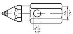
The drawing beside shows an atomizing head assembled onto one A type Holder
| Degree | Setup Code |
|
Air pressure (bar) |
||||
NOZZLE |
WM | AH |
WM | AH |
WM | AH |
WM | AH |
WM | AH |
||
| 25° | EEI 0331 B1 | 2 3 4 5 6 |
0,10 | 3,1 0,05 | 3,7 0,02 | 4,7 - | - - | - |
0,12 | 3,0 0,10 | 3,1 0,05 | 4,8 0,02 | 5,3 - | - |
0,15 | 3,1 0,12 | 3,6 0,08 | 4,4 0,05 | 5,3 0,02 | 6,1 |
0,27 | 2,7 0,20 | 3,7 0,18 | 4,4 0,13 | 5,5 0,12 | 6,0 |
- | - 0,32 | 2,9 0,25 | 4,2 0,22 | 5,2 0,18 | 5,8 |
| 25° | EEI 0801 B1 | 2 3 4 5 6 |
0,23 | 2,7 0,22 | 3,6 0,18 | 4,5 0,12 | 5,4 0,07 | 6,2 |
0,28 | 2,9 0,27 | 3,6 0,22 | 4,4 0,18 | 5,3 0,13 | 6,3 |
0,37 | 2,7 0,32 | 3,5 0,28 | 4,6 0,25 | 5,6 0,22 | 6,2 |
0,72 | 2,2 0,52 | 3,2 0,45 | 4,6 0,40 | 5,4 0,35 | 6,3 |
- | - 0,82 | 2,7 0,62 | 4,7 0,53 | 5,4 0,50 | 6,2 |
| 25° | EEI 1131 B1 | 2 3 4 5 6 |
0,50 | 7,3 0,40 | 9,7 0,27 | 11,6 0,13 | 13,9 0,07 | 18,6 |
0,60 | 6,6 0,50 | 9,5 0,37 | 11,9 0,23 | 13,8 0,13 | 18,7 |
0,73 | 6,9 0,65 | 9,4 0,55 | 11,8 0,38 | 14,0 0,27 | 8,7 |
1,15 | 5,6 0,96 | 9,3 0,93 | 12,1 0,87 | 14,1 0,72 | 18,9 |
- | - 1,35 | 7,9 1,20 | 11,5 1,15 | 13,8 1,10 | 19,0 |
| 45° | EEI 0800 B1 | 2 3 4 5 6 |
0,18 | 2,7 0,15 | 3,7 0,10 | 4,5 0,03 | 5,4 - | - |
0,23 | 2,7 0,18 | 3,9 0,17 | 4,6 0,10 | 5,6 0,03 | 6,2 |
0,32 | 2,9 0,25 | 3,5 0,22 | 4,9 0,18 | 5,4 0,12 | 6,3 |
0,73 | 2,1 0,50 | 3,7 0,33 | 4,8 0,30 | 5,4 0,27 | 6,2 |
- | - 0,85 | 2,6 0,53 | 4,4 0,45 | 5,3 0,38 | 6,3 |
| 45° | EEI 1130 B1 | 2 3 4 5 6 |
0,46 | 7,3 0,38 | 9,5 0,23 | 11,8 0,13 | 13,5 0,07 | 16,0 |
0,52 | 7,2 0,47 | 9,7 0,35 | 11,8 0,23 | 13,9 0,13 | 16,2 |
0,68 | 6,8 0,65 | 10,2 0,50 | 11,9 0,37 | 14,0 0,27 | 16,2 |
1,13 | 5,7 0,95 | 9,4 0,88 | 12,1 0,82 | 14,1 0,63 | 16,2 |
- | - 1,27 | 7,7 1,15 | 11,8 1,10 | 14,2 1,03 | 16,3 |
| 45° | EEI 1300 B1 | 2 3 4 5 6 |
0,95 | 14,6 0,80 | 19,3 0,60 | 24,7 0,42 | 29,9 0,23 | 35,6 |
1,12 | 16,5 1,00 | 20,0 0,80 | 24,7 0,60 | 30,3 0,40 | 36,0 |
1,40 | 16,3 1,26 | 22,2 1,08 | 25,0 0,90 | 30,4 0,67 | 35,6 |
2,42 | 10,4 1,90 | 19,2 1,80 | 25,0 1,70 | 30,5 1,55 | 36,2 |
- | - 2,87 | 14,5 2,40 | 23,2 2,27 | 29,9 2,15 | 35,2 |
| Liquid pressure (bar) | 0,5 | 0,7 | 1,0 | 2,0 | 3,0 | ||
|
IDENTIFICATION CODES :
DRY FOG NOZZLE HEAD
The codes given in the table refer to the atomizing head only, and can be used to order the head as a separate part.
HOLDER
Can be ordered separately using the codes below, please replace
XX = B1 for AISI 303
XX = T1 for brass
COMPLETE DRY FOG NOZZLE
To identify a complete nozzle, please add to the head code the two suffix letters describing the adapter material and the Holder style according to the information below.
Y
Holder Material
A = T1 Brass
B = B1 AISI 303
Z
Holder style
A = XMA 0103 xx
B = XMA 0101 xx
C = XMA 0102 xx
D = XMA 0100 xx

HOLDER STYLE A
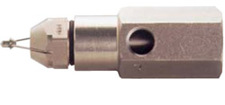
HOLDER STYLE B
HOLDER STYLE B

HOLDER STYLE B
Type A holder style allow for mounting the atomizer through a wall or the side of a duct.
In this case do not forget to order the VAC 0021 B1 locknut, which fits both, to hold the adapter in place.
Related products
-
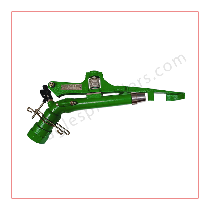
Sprinklers ES – 65PC
₹0.00 -
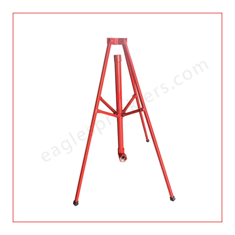
Sprinkler Stand
₹0.00 -
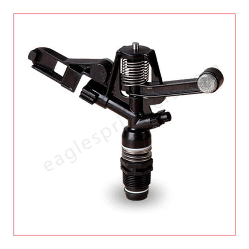
Sprinklers 3/4 02
₹0.00


